What is flash steam and why should it be used?
'Flash steam' is released from hot condensate when its pressure is reduced. Even water at an ambient room temperature of 20°C would boil if its pressure were lowered far enough. It may be worth noting that water at 170°C will boil at any pressure below 6.9 bar g. The steam released by the flashing process is as useful as steam released from a steam boiler.
As an example, when steam is taken from a boiler and the boiler pressure drops, some of the water content of the boiler will flash off to supplement the 'live' steam produced by the heat from the boiler fuel. Because both types of steam are produced in the boiler, it is impossible to differentiate between them. Only when flashing takes place at relatively low pressure, such as at the discharge side of steam traps, is the term flash steam widely used. Unfortunately, this usage has led to the erroneous conclusion that flash steam is in some way less valuable than so-called live steam.
In any steam system seeking to maximise efficiency, flash steam will be separated from the condensate, and used to supplement any low pressure heating application. Every kilogram of flash steam used in this way is a kilogram of steam that does not need to be supplied by the boiler. It is also a kilogram of steam not vented to atmosphere, from where it would otherwise be lost.
The reasons for the recovery of flash steam are just as compelling, both economically and environmentally, as the reasons for recovering condensate.
How much flash steam is available?
If use is to be made of flash steam, it is helpful to know how much of it will be available. The quantity is readily determined by calculation, or can be read from simple tables or charts.
Example 14.6.1 - Consider the jacketed vessel shown in Figure 14.6.1
The condensate enters the steam trap as saturated water, at a gauge pressure of 7 bar g and a temperature of 170°C. The specific amount of heat in the condensate at this pressure is 721 kJ/kg.
After passing through the steam trap, the pressure in the condensate return line is 0 bar g. At this pressure, the maximum amount of heat each kilogram of condensate can hold is 419 kJ and the maximum temperature is 100°C. There is an excess of 302 kJ of heat which evaporates some of the condensate into steam. The quantity of steam is calculated in the following text.
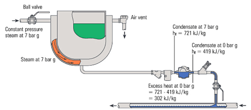
Fig. 14.6.1 Excess heat in condensate produces flash steam
The heat needed to produce 1 kg of saturated steam from water at the same temperature, at 0 bar gauge, is 2257 kJ. An amount of 302 kJ can therefore evaporate:
From each kilogram of condensate in this example, the proportion of flash steam generated therefore equals 13.4% of the initial mass of condensate.
If the equipment using steam at 7 bar g were condensing 250 kg/h, then the amount of flash steam released by the condensate at 0 bar g would be:
0.134 x 250 kg/h of condensate = 33.5 kg/h of flash steam
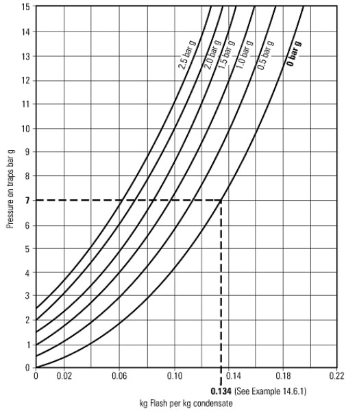
Alternatively, the chart in Figure 14.6.2 can be read directly for the moderate and low pressures encountered in many plants.
The example shown in Figure 14.6.1 is depicted in Figure 14.6.2 and shows that 0.134 kg of flash steam is produced per kg of condensate passing through the trap.
Fig. 14.6.2 Flash steam graph
Sub-cooled condensate
If the steam trap is of a thermostatic type, the discharged condensate is sub-cooled below saturation temperature. The heat in the cooler condensate will be slightly less, and the amount of flash steam produced would be less.
If the trap in Example 14.6.1 discharged condensate at 15°C below the steam saturation temperature, then the available heat in the condensate would be less.
Example 14.6.2 Consider condensate discharging at 7 bar g and with 15°C of subcooling
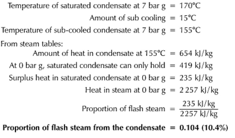
Therefore, in this example, condensate discharging at a temperature lower than the saturation temperature has reduced the proportion of flash steam from 13.4% to 10.4%.
Pressurised condensate
Example 14.6.3 Consider the condensate in Example 14.6.1 discharging to a flash vessel pressurised at 1 bar g
If the return line were connected to a vessel at a pressure of 1 bar g, then it could be seen from steam tables that the maximum heat in the condensate at the trap discharge would be 505 kJ/kg and the enthalpy of evaporation at 1 bar g would be 2201 kJ/kg.
The proportion of the condensate flashing off at 1 bar g can then be calculated as follows:
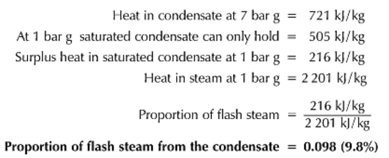
In this example, if the equipment using steam at 7 bar g were condensing 250 kg/h of steam, then the amount of flash steam released by the condensate at 1 bar g would be 0.098 x 250 kg/h = 24.5 kg/h of flash steam.
Therefore, the amount of flash steam produced can depend on the type of steam trap used, the steam pressure before the trap, and the condensate pressure after the trap.
 Top Top
The flash steam recovery vessel (flash vessel)
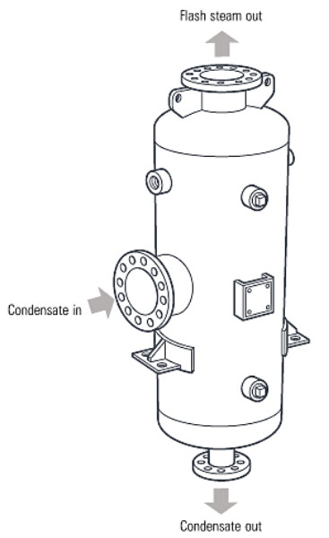
Flash vessels are used to separate flash steam from condensate. Figure 14.6.3 shows a typical flash vessel constructed in compliance with the European Pressure Equipment Directive 97/23/EC.
After condensate and flash steam enter the flash vessel, the condensate falls by gravity to the base of the vessel, from where it is drained, via a float trap, usually to a vented receiver from where it can be pumped. The flash steam in the vessel is piped from the top of the vessel to any appropriate low pressure steam equipment.
Fig. 14.6.3 A typical flash vessel constructed to European standards
Sizing flash steam recovery vessels
To size a flash vessel, the following information is required:
- The steam pressure before the steam trap(s) supplying the vessel.
- The total condensate flowrate into the flash vessel.
- The flash steam pressure in the flash vessel.
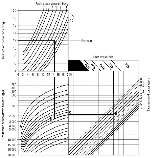
Using this information, together with a flash vessel sizing chart (see Figure 14.6.4), the size of the vessel can be determined. Example 14.6.4 demonstrates flash vessel sizing, using a chart.
Example 14.6.4 Determine the size of a flash vessel to suit the following conditions:
The pressure onto the steam traps is 12 bar g with a total condensate flow of 2500 kg/h. The flash steam from the vessel is to be supplied to equipment using low pressure steam at 1 bar g.
Method:
1. From the 'Pressure on steam traps' axis at 12 bar g, move horizontally to the 1 bar g flash steam pressure curve at point A.
2. Drop down vertically to the condensate flowrate level of 2500 kg/h, point B, and follow the curved line to point C.
3. Move right from point C to meet the 1 bar g flash line at point D.
4. Move upwards to the flash vessel size and select the vessel.
For this example, an FV8 flash vessel would be selected.
Fig. 14.6.4 Flash vessel sizing chart
Requirements for successful flash steam applications
If full use is to be made of flash steam, some basic requirements must be satisfied:
- It is essential to have a continual supply of sufficient condensate from applications operating at higher pressures, to ensure that enough flash steam can be released for economic recovery.
- The steam traps and the equipment they are draining must be able to function satisfactorily against the backpressure applied by the flash system.
- Care must be taken when attempting flash steam recovery with condensate from temperature controlled equipment. At less than full-load, the steam space pressure will be lowered by the closing action of the steam control valve. If the steam pressure in the equipment approaches or falls below the specified flash steam pressure, the overall amount of flash steam formed will be marginal, and one must question whether recovery is worthwhile in this instance.
- It is important that there is a demand for low pressure flash steam that either equals or exceeds the flash steam being produced. Any deficit of flash steam can be made up by live steam from a pressure reducing valve. If the supply of flash steam exceeds its demand, surplus pressure will be created in the flash steam distribution system, which will then have to be vented to waste through a surplussing valve.
- It is possible to utilise the flash steam from condensate on a space heating installation - but savings will only be achieved during the heating season. When heating is not required, the recovery system becomes ineffective. Wherever possible, the best arrangement is to use flash steam from process condensate to supply process loads - and flash steam from heating condensate to supply heating loads. Supply and demand are then more likely to remain in-step.
- It is preferable to actually use the flash steam close to the high pressure condensate source. Relatively large diameter pipes are used for low pressure steam, to reduce pressure loss and velocity, which can mean costly installation if the flash steam has to be piped any distance.
Control of flash steam pressure
Another consideration is a method of controlling the pressure of the flash steam.
In some cases, flash pressure will find its own level and nothing more needs to be done. When supply and demand are always in-step, and particularly if the low pressure steam is used on the same equipment producing the high pressure condensate, it is only neccessary to pipe the flash steam to the low pressure plant without any other control.
Figure 14.6.5 shows the application of flash steam recovery to a multi-bank air heater battery, which is supplying high temperature air to a process. Condensate from the high pressure sections is taken to the flash vessel, from where the low pressure flash steam is used, to preheat the cold air entering the battery via the frost coil (preheater). The surface area of the preheater section, and the relatively low temperature of the incoming air, will mean that the low pressure flash steam is readily condensed.
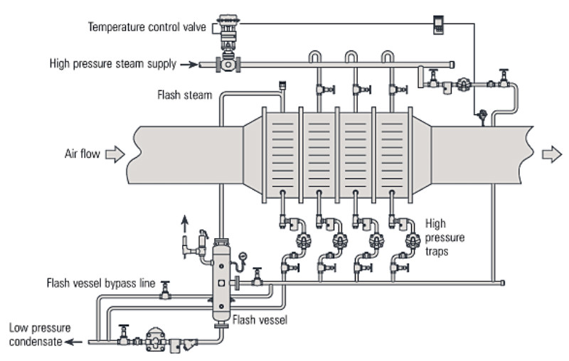 Fig. 14.6.5 Flash steam recovery on a multi-bank air heater battery Fig. 14.6.5 Flash steam recovery on a multi-bank air heater battery
Depending on operating temperatures, the flash steam will condense at some low pressure, perhaps even sub-atmospheric. If site conditions and layout permit, the flash vessel and the steam trap draining the preheater should be located far enough below the preheater condensate outlet to give enough hydrostatic head to push the condensate through the trap. If this is not possible, pumping traps can be used to drain both the preheater coil and the flash vessel.
Steam condensing in the preheater at sub-atmospheric pressure will generally mean that a vacuum breaker is required on the flash steam supply to the preheater. This will prevent the pressure in the battery becoming sub-atmospheric, thereby assisting condensate flow to the trap. Drainage from the preheater trap is induced by gravity flow.
Figure 14.6.6 shows an application where the flash steam system is kept at a specified constant pressure by steam fed from a reducing valve. This ensures a reliable source of steam to the low pressure system if there is a lack of flash steam to meet the load.
Top
Typical applications for flash steam
Flash steam supply and demand in-step
This gives maximum utilisation of the available flash steam. The air heater battery discussed in Figure 14.6.5 is one such system, but similar arrangements are practical with many other applications such as space heating installations using either radiant panels, or unit heaters.
Figure 14.6.6 depicts a system where a number of heaters are supplied with high pressure steam. The condensate from approximately 90% of the heaters is collected and taken to a flash recovery vessel. This supplies low pressure steam to the remaining 10% of the heaters.
With this system, the total heat output of the system is marginally reduced, as 10% of the heaters are operating at a lower steam pressure. However, it is rare to find an installation that does not have a sufficient margin of output above the normal load to accept this small reduction.
Sometimes a problem arises where the use of available flash steam may require more than one heater but less than two. It would be better in this case to connect two heaters to the flash steam supply, rather than vent the excess flash steam off to waste. Two heaters together will usually pull the flash pressure down to a lower level, even to sub-atmospheric levels. To cope with this, the supply of flash steam can be supplemented with live steam from a pressure reducing valve.
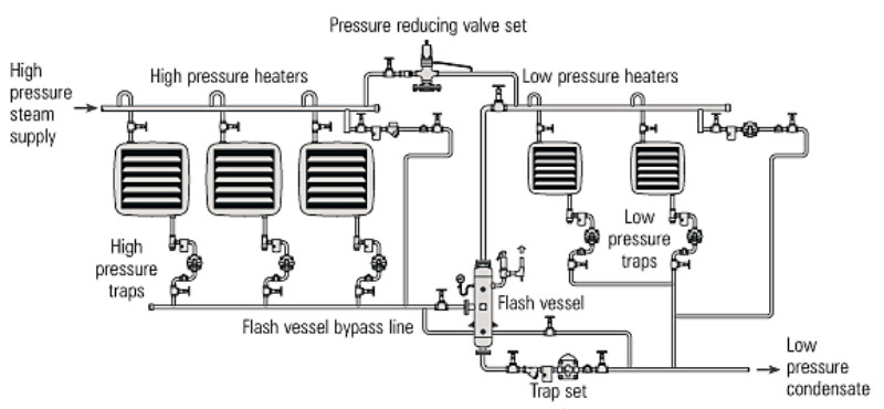
Fig. 14.6.6 Flash steam supply and demand in step
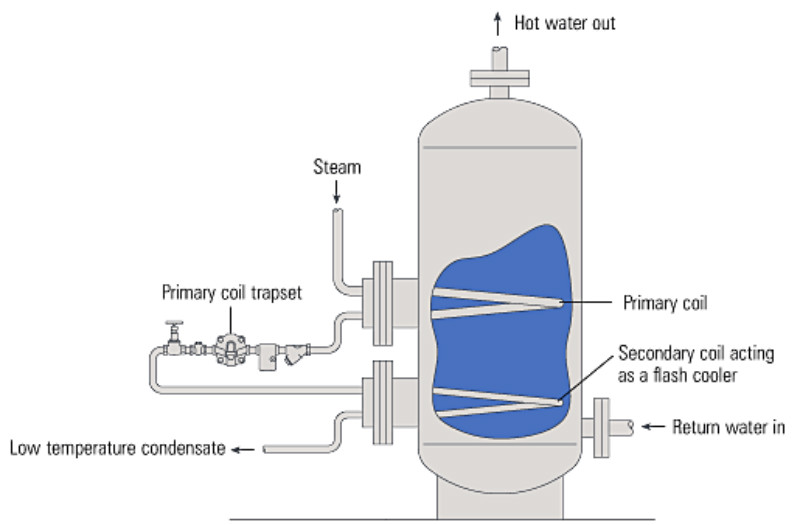
Another example where supply and demand are 'in step' is the steam heated hot water storage calorifier. Some of these incorporate a second coil, fitted close to the bottom of the vessel adjacent to where the cold feedwater enters.
Condensate and flash steam from the trap on the primary coil is passed directly to the secondary coil. Here, any flash steam produced by the drop in pressure across the trap is condensed, while giving up its heat to the feedwater. A typical arrangement is shown in Figure 14.6.7.
Fig. 14.6.7 Secondary flash steam coil in a storage calorifier
Another example of this idea is shown in Figure 14.6.8. Here, a normal steam-to-water calorifier drains condensate through a float trap to a smaller shell-and-tube heat exchanger (called a flash condenser), in which the flash steam is condensed to sub-cooled condensate. The unit is fitted such that the secondary flow pipework is in series with both calorifier and condenser. This enables the secondary return water to be preheated by the condenser, thereby reducing the demand for live steam in the first instance.
If the condensate in the flash condenser is likely to be sub-atmospheric, a mechanical pump is required to lift the condensate to any higher return line. The motive steam exhausting from the pump is itself condensed in the flash condenser. The pumping of the condensate is then achieved at virtually no cost.
Consideration must be given to the pump filling head in that it needs to be greater than the pressure drop across the flash condenser tubes under full-load conditions. A minimum head of 600 mm will usually achieve this.
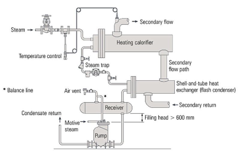
Fig. 14.6.8 Packaged calorifier and flash condenser unit
Flash steam supply and demand not in-step
The arrangement in Figure 14.6.9 is an example of flash steam recovery where the supply and demand are not always 'in-step'.
Condensate from three jacketed pans and a drain pocket releases flash steam, but it can only be used to augment the supply of steam to the space heating installation. This is quite satisfactory during the heating season, as long as the heating load exceeds the availability of flash steam.
During the summer season the heating equipment will not be in use, and even during spring and autumn the heating load may not be able to use all the available flash steam. The arrangement is not ideal, although it is quite possible for the steam savings made during the winter to justify the cost of the flash steam recovery equipment.
Sometimes, surplus flash steam must be vented to atmosphere, and, as indicated, a surplussing valve is more suitable for this purpose than a safety valve, which usually has a 'pop' or 'on / off' action and a seat arrangement designed for infrequent operation. The surplussing valve will be set so that it begins to open slightly above the normal pressure in the system. When the heating load falls and the pressure in the system begins to increase, the pressure reducing valve supplying the make-up steam closes down. A further increase of pressure, perhaps of 0.15 to 0.2 bar, is then allowed before the surplussing valve begins to open to release the excess flash steam.
A safety valve may still be required if the surplussing valve fails. It must be set to open at a pressure between the surplussing valve set pressure and the system design pressure. It is usually convenient to fit the safety valve onto the flash vessel.
Occasionally, during summer conditions it may be preferable to bypass the flash system with a manual valve (not shown in Figure 14.6.9). The condensate and its associated flash steam will then pass directly to a condensate receiver, where the flash steam will be vented to atmosphere.
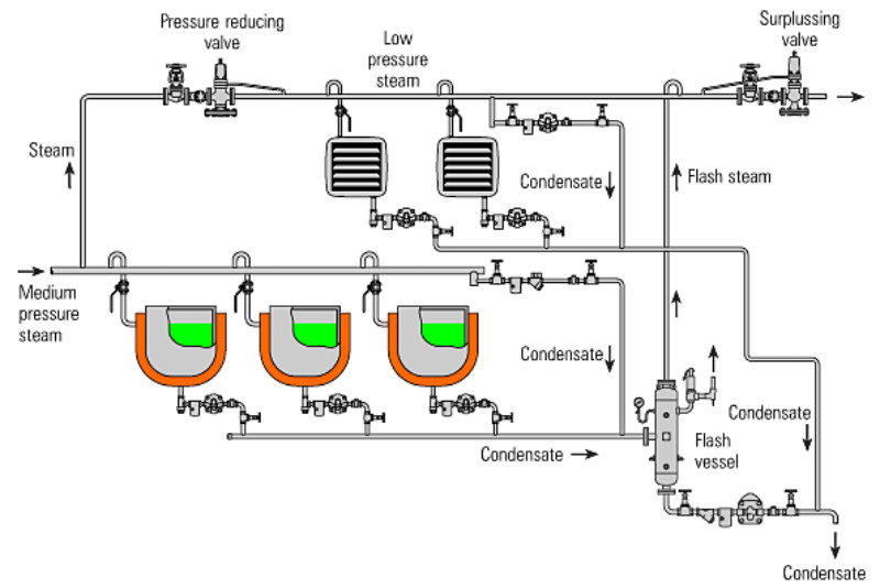
Fig. 14.6.9 Flash steam supply and demand not in-step
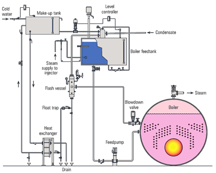
Boiler blowdown heat recovery applications
Continuous blowdown of boiler water is necessary to control the level of TDS (Total Dissolved Solids) within the boiler. Continuous blowdown lends itself to the recovery of the heat content of the blowdown water and can enable considerable savings to be made.
Boiler blowdown contains massive quantities of heat, which can easily be recovered as flash steam. After it passes through the blowdown control valve, the lower pressure water flows to a flash vessel. At this point, the flash steam is free from contamination and is separated from the condensate, and can be used to heat the boiler feedtank (see Figure 14.6.10).
The residual condensate draining from the flash vessel can be passed through a plate heat exchanger in order to reclaim as much heat as possible before it is dumped to waste. Up to 80% of the total heat contained in boiler continuous blowdown can be reclaimed in this way.
Fig. 14.6.10 Typical heat recovery from boiler blowdown
Spray condensing
Finally, consideration should be given to those cases where flash steam is unavoidably generated at low pressure, but where no suitable load is available which can make use of it.
Rather than simply discharge the flash steam to waste, the arrangement in Figure 14.6.11 can often be adopted.
This arrangement can be useful where the condensate receiver vent cannot be piped to outside, and where the presence of flash steam would be detrimental if left to discharge in a plant room.
A lightweight stainless steel chamber is fitted to the receiver tank vent. Cold water is sprayed into the chamber in sufficient quantities to just condense the flash steam. The flow of cooling water is controlled by a simple self-acting temperature control, adjusted so that minimal amounts of flash steam appear from the vent. The process will use roughly 6 kilograms of cooling water per kilogram of flash steam condensed.
If the cooling water is of boiler feed quality, then the warmed water is added to the condensate in the receiver and re-used. This will continue to make water savings throughout the year.
If the cooling water is not suitable for recovery, the spray pipework can be installed as shown by the dotted arrangement. The cooling water and condensed flash will then fall to waste.
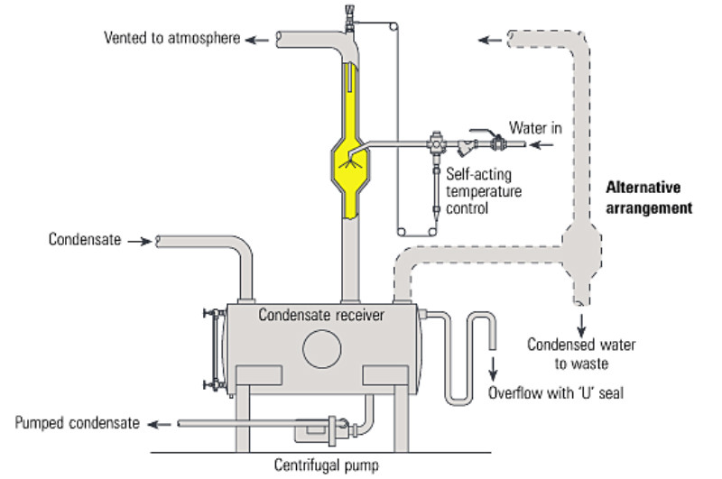
Fig 14.6.11 Flash steam condensing and water saving by spray
|